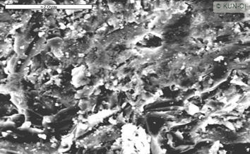
At a 1 μm scale.
A closer surface view.
The detailed image records local surface morphology. The original scale bar, detector, working distance, accelerating voltage and date remain visible at the bottom.

Stainless steel micro surface treatment for your components. Send us your requirements for assessment and a quotation, from samples to batch production.
View the test evidence ↓KUN-QI provides SMT stainless steel micro surface treatment, focusing on surface structure, smoothness and cleanliness. Enquiries may concern precision components with holes, threads, internal walls, flat or curved surfaces. Medical instruments and industrial components with roughness, cleanliness or corrosion-resistance requirements are assessed against their material, geometry and intended use. The microscopy and test records below support that assessment; suitability is reviewed for each component.
Two treated-surface images. Two viewing scales.
The original scale bars and instrument information remain intact.
The detailed image records local surface morphology. The original scale bar, detector, working distance, accelerating voltage and date remain visible at the bottom.
The wider image adds context to the surface observation. Both images show SMT-treated surfaces: they are not a before-and-after pair and should not be compared without considering their scale bars.
The fem profilometry report records three Ra readings of 0.02 μm for the SMT-treated component, with a mean of 0.02 μm, equivalent to 20 nm.
(20 nm)
Test Results from fem, Germany
| Report specimen | Reading 1 | Reading 2 | Reading 3 | Mean |
|---|---|---|---|---|
| SMT-treated component | 0.02 | 0.02 | 0.02 | 0.02 |
Readings and the mean retain the precision shown in the report. The SMT-treated component has a mean Ra of 0.02 μm, equivalent to 20 nm.
Test Results from fem, Germany
NSS salt-spray testing: photographic records of stainless steel specimens at 500 h and 1000 h.
Examine the post-oxidation surface with the original electron micrographs and their respective test conditions.
Test Results from fem, Germany
The SMT-treated stainless steel components are shown before exposure, after 500 hours and after 1000 hours. The original specimen appearance and exposure-time markers are retained.
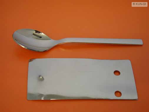
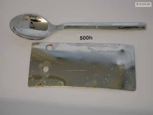
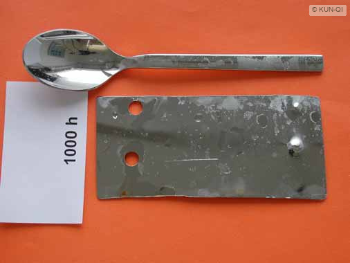
These are photographic records at the stated NSS exposure times; the photographs alone do not specify a corrosion rating or pass/fail assessment.
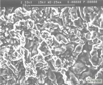
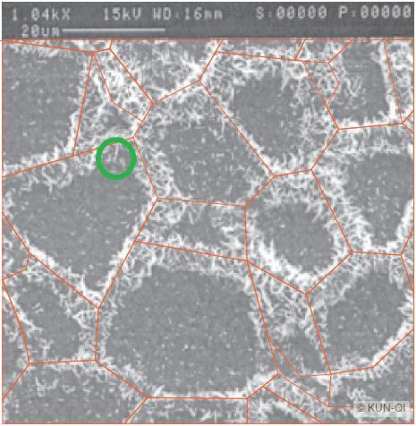
Oxidation conditions: untreated surface, 950°C / O₂; SMT-treated surface, 900°C / ArH₂–H₂O. Atmosphere, temperature and instrument magnification differ; these are not matched-condition comparison images.
The lotus effect is presented here as a natural example of how microscopic surface structure can influence water and surface interactions. It provides a conceptual introduction to surface structure, adhesion and cleanability.
This natural example does not establish that SMT-treated surfaces are necessarily superhydrophobic or have the same water-droplet contact angle as a lotus leaf. Contact-angle and roll-off-angle data have not been provided; the concept image and micrographs do not substitute for wetting measurements.
Return to the original micrographs ↗
Bacterial Retention Testing: Labor Dr. Gärtner, Ravensburg, Germany
SMT surface micro-treatment reduces opportunities for bacterial adhesion. In this MRSA test, the SMT-treated panel retained fewer colonies after the specified wiping procedure than the untreated and electropolished panels.
| Surface condition | Residual CFU |
|---|---|
| Before Treatment | 12 |
| Electropolished | 220 |
| After SMT Treatment | 4 |
Under the procedure described above, the SMT panel had the lowest residual CFU. CFU means colony-forming units and records residual colonies after wiping; it is not a sterilisation rate.
The SMT instrument reprocessing test documentation records that SMT-treated medical instruments underwent 73 cleaning cycles under conditions comparable to those encountered during sterilisation. The reported result was a corrosion-free, smooth surface.
73 cycles is the documented observation point, not a failure count or service-life limit. The document does not report failure after the 73rd cycle.
The following before-and-after images are a separate instrument reconditioning case in the same documentation. They are not paired photographs from the 73-cycle test described above.
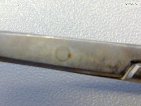
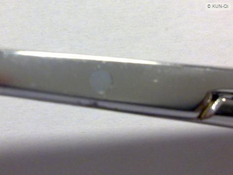
SMT processing time is adjusted to component requirements, with attention to internal surface smoothness and consistency within a defined area. Submit a component for sample assessment ↗
Both images show SMT treatment at different processing times. SMT focuses on maintaining component dimensions while achieving a smoother, more refined surface. Measured Ra surface roughness can reach 0.02 μm (20 nm); see the Ra measurement section on this page. Original magnification, 100 μm scale bars and red arrows are retained.
Internal surface observation at a different SMT processing time.
Internal surface observation at a different SMT processing time.
The overall component dimensions are 600 × 600 mm. The internal Ø 12 inch circle is the specified treatment area, within which consistent surface treatment results are required.
Threads, curves and bores. A closer view of SMT surface refinement.
Surface refinement across planes and bore edges.
A closer look at threads and internal surfaces.
Light reveals the transitions between curved surfaces and faces.
SMT component photographs supplied by KUN-QI.
No. The μm scale bars describe the lateral viewing scale. Ra is a measured surface roughness parameter and cannot be calculated directly from these photographs.
The original embedded images were extracted from the supplied test documents. The source images retain their original framing, colours and scale bars. Public web copies carry a discreet © KUN-QI mark; the technical data have not been altered.
Material, geometry, initial surface, service environment and acceptance criteria require review. The documented specimens and tests do not establish guaranteed values for every component.
Send us your component requirements so we can assess the most suitable treatment.
We assess sample and batch enquiries individually. Feasibility, scope, lead time and price are confirmed after review.